
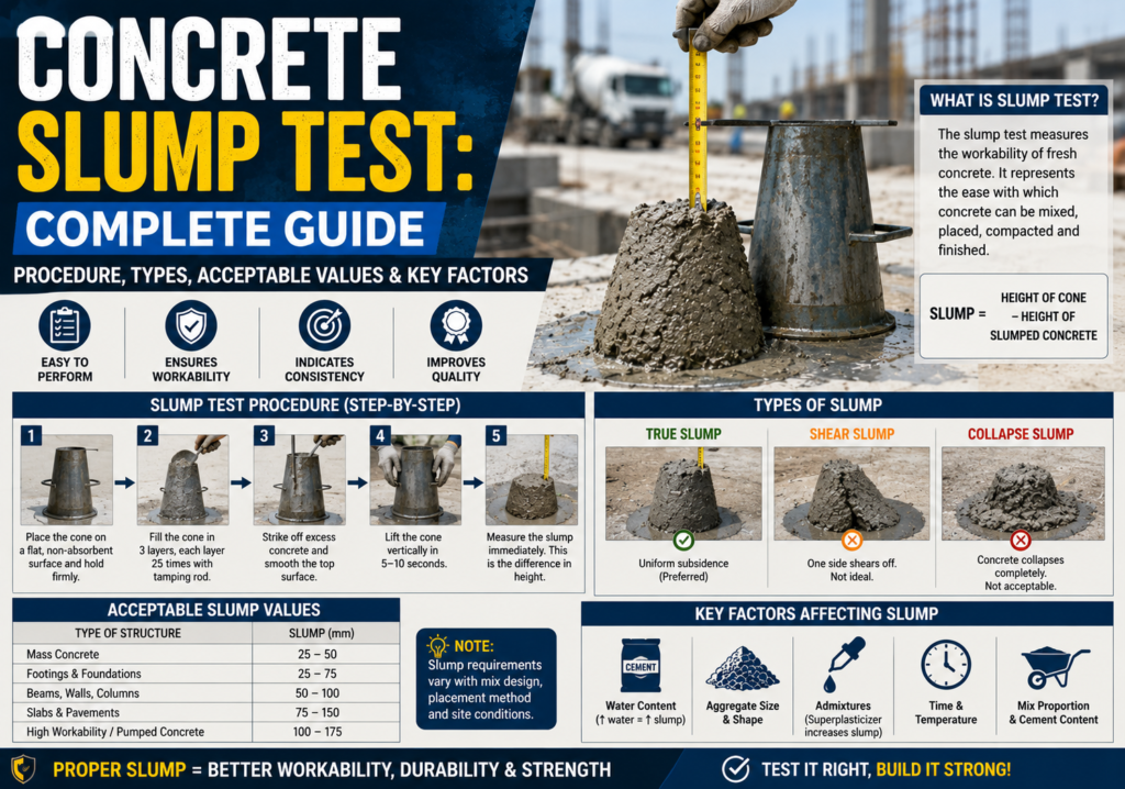
The concrete slump test measures how workable fresh concrete is before it sets. In plain terms: it tells you whether your concrete mix will actually flow into forms, wrap around rebar, and compact without leaving voids or whether it will give you trouble on site.
Run the test wrong, and you end up placing concrete that’s too stiff to compact properly, or so wet it bleeds water and loses strength. Both scenarios mean structural problems later.
This guide walks through the exact procedure, the 3 slump types you’ll see in the field, acceptable value ranges for every application, and the 6 factors that shift your slump reading up or down. Whether you’re a site engineer, contractor, or student — this is the complete reference.
What Is the Concrete Slump Test?
The concrete slump test (also called the slump cone test or Abrams cone test) is a standardized field test that measures the consistency and workability of freshly mixed concrete by filling a conical mold, lifting it off, and measuring how much the concrete drops (slumps) in millimeters.
The test has been in use since 1918, when American civil engineer Duff Abrams introduced it as part of his research on the water-to-cement ratio and concrete strength. The original cone is still called the Abrams cone in his honor.
It runs under 3 international standards:
- ASTM C143 — Standard Test Method for Slump of Hydraulic-Cement Concrete (United States)
- IS 1199:1959 — Indian Standard for sampling and analysis of concrete
- BS EN 12350-2 — European Standard (replaced BS 1881-102 in the UK)
Why the Slump Test Matters on Every Job Site
A concrete mix that looks right may still be wrong. Temperature, transit time, aggregate moisture, and admixture dosage all shift workability batch to batch. The slump test catches those shifts before pour — not after. It’s your 2-minute quality gate.
Slump Test Equipment: 5 Items You Need
ASTM C143 requires 5 pieces of equipment. Nothing expensive, nothing complex — but every item must meet spec:
| Equipment | Specification / Dimension |
| Slump Cone (Abrams Cone) | Height: 300 mm | Bottom Ø: 200 mm | Top Ø: 100 mm |
| Tamping Rod | Diameter: 16 mm | Length: 600 mm | Hemispherical tip |
| Base Plate | Flat, non-absorbent metal plate |
| Ruler / Tape Measure | Measure to nearest 5 mm (¼ inch) |
| Scoop / Trowel | For filling the cone uniformly |
Critical note on the tamping rod: It must have a hemispherical (rounded) tip. Using rebar or a flat rod pushes aggregate particles down instead of uniformly consolidating the mix. This invalidates the test.
Concrete Slump Test Procedure: 7 Steps (ASTM C143)
Complete the entire test within 2.5 minutes of sampling. Set up your equipment first — the clock starts when you take the sample.
Step 1: Sample the Concrete
Take a composite sample from the middle portion of a batch discharge, collecting 2 or more portions within a 15-minute window. For pump discharge or concrete buckets, sample at the point of placement. Start the 5-minute timer — slump, air content, and temperature tests must begin within 5 minutes of sampling.
Step 2: Prepare the Equipment
Place the slump cone on a flat, non-absorbent, vibration-free surface. Dampen the inside of the cone and the base plate — no excess water. Secure the cone by standing on the foot tabs or clamping it to the base plate.
Step 3: Fill the Cone in 3 Layers
Fill the mold in 3 layers of equal volume (not equal depth). Equal-volume depths work out to approximately:
- Layer 1: 70 mm (2⅝ inches) from the bottom
- Layer 2: 160 mm (6⅛ inches) from the bottom
- Layer 3: to the top of the cone
Step 4: Rod Each Layer 25 Times
Compact each layer with 25 evenly distributed strokes using the tamping rod. Start around the perimeter and spiral toward the center. For the bottom layer, rod without forcefully striking the base plate. For subsequent layers, penetrate 25 mm (1 inch) into the layer below.
Never tap the cone. Any tapping, movement, or vibration of the cone means discard the sample and start fresh.
Step 5: Strike Off the Top
After rodding the third layer, strike off excess concrete flush with the top of the cone using a rolling motion of the tamping rod.
Step 6: Lift the Cone Cleanly
Remove excess concrete from around the base of the cone. Lift the cone straight up — no twisting — in 5 ± 2 seconds. The unsupported concrete will now slump under its own weight.
Step 7: Measure the Slump
Measure the vertical difference between the top of the mold and the displaced center of the top of the slumped concrete, to the nearest 5 mm (¼ inch). Record this as the slump value. If a portion of the specimen shears away, discard and retest with a new sample.
Time Limits to Know
Sampling to test start: within 5 minutes. Complete test from sampling: within 2.5 minutes. Exceeding these limits makes results unreliable — concrete begins losing workability through hydration the moment you sample.
3 Types of Concrete Slump Explained
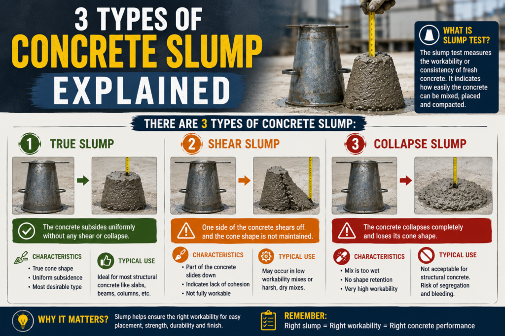
Once you lift the cone, the shape of the settled concrete tells you something specific about the mix. There are 3 outcomes:
1. True Slump
True slump is the only valid result. The concrete mass drops evenly and symmetrically from all sides, maintaining a rounded top. This is the outcome you want. Measure the vertical drop at the center.
2. Shear Slump
One side of the concrete shears off and slides laterally. This indicates poor cohesion in the mix — the ingredients are not bonding properly. Discard this result, take a fresh sample, and retest. If the shear slump repeats, the mix needs adjustment.
3. Collapse Slump
Collapse slump means the concrete flattens completely. This shows the mix is too wet (water-cement ratio too high) or is a high-workability mix for which the standard slump test is not appropriate. Use the flow table test (EN 12350-5) for very high-workability mixes instead.
Concrete Slump Values: Acceptable Ranges by Application
The right slump depends on where and how the concrete is being placed. Use this table as your site reference:
| Concrete Use / Application | Slump (mm) | Slump (inches) |
| Plain footings, caissons, subbase | 25–75 mm | 1–3 in |
| Foundation walls & footings (lightly reinforced) | 50–100 mm | 2–4 in |
| Beams, walls, slabs | 75–125 mm | 3–5 in |
| Columns, heavily reinforced sections | 100–150 mm | 4–6 in |
| Pumped concrete / flowing concrete | ≥ 150 mm | ≥ 6 in |
| Road pavements, vibrated lean concrete | 10–30 mm | 0.4–1.2 in |
Key rule: A slump above 200 mm risks segregation. Below 25 mm, compaction becomes difficult without proper vibration equipment. Most project specs allow a tolerance of ±25 mm from the target value.
6 Factors That Affect Concrete Slump
Slump is not fixed — it shifts based on 6 controllable variables. Knowing them helps you diagnose unexpected results and correct them fast.
1. Water-to-Cement Ratio
More water = higher slump. This is the strongest single factor. However, every extra liter of water per cubic meter reduces compressive strength and increases porosity. Adding water to boost slump on site is a common but damaging shortcut — it makes concrete weaker, more porous, and more vulnerable to freeze-thaw damage.
2. Aggregate Size and Shape
Larger aggregates produce higher slump with the same water content because they have lower surface area. Rounded, smooth aggregates are more workable than angular, flaky ones — they create less internal friction. Well-graded aggregate mixes tend to produce more consistent slump results.
3. Chemical Admixtures
Superplasticizers (high-range water reducers) increase slump by 100–200 mm without adding water. This is the correct way to boost workability for pumped concrete, densely reinforced sections, or hot weather pours. Regular plasticizers typically give 30–60 mm slump increase with 10–15% water reduction. Air-entraining admixtures slightly improve workability as tiny air bubbles act as ball bearings in the mix.
4. Cement Properties and Content
Finer cements (higher specific surface area) absorb water faster, which initially increases slump but accelerates slump loss over time. Higher cement content mixes tend to be slightly more workable due to increased paste volume surrounding aggregates.
5. Temperature
Hot weather is the enemy of slump. Every 10°C rise in concrete temperature cuts slump by approximately 25 mm. In summer pours, plan for this by chilling mixing water, shading aggregates, or scheduling pours for early morning. Cold weather slows hydration and retains slump longer but creates other placement issues.
6. Time After Mixing
Slump drops continuously from the moment water contacts cement. Ready-mix concrete loses approximately 25 mm of slump per 30 minutes in transit. This is why transit time from batching plant to pour point matters — always slump test at point of delivery, not at the plant.
Limitations of the Slump Test
The slump test works best for concrete with slump values between 25 mm and 150 mm. It has 4 specific limitations:
- Not suitable for very stiff mixes (zero slump) — cannot distinguish between different levels of stiffness in dry concrete
- Not suitable for very wet mixes (collapse slump ≥ 175 mm) — use the flow table test instead
- Not valid for concrete with maximum aggregate size above 38 mm (1.5 inches)
- Gives no direct measurement of water-cement ratio — two mixes with different admixtures can show the same slump with very different strengths
For mixes outside these limits, engineers use the Vee-Bee consistometer test (very stiff mixes), the compaction factor test (wide range), or the flow table test (self-compacting concrete).
Why Slump Testing Matters for Roofing and Waterproofing Projects
Concrete quality directly affects roofing structures. Parapet walls, roof decks, concrete tile underlayment, and flat-roof structural slabs all depend on properly tested concrete to prevent water infiltration. A mix that was too wet on pour day will be porous and crack-prone years later — creating exactly the leaks that require professional roof repair services.
Flat roofs built on concrete structural decks are especially vulnerable. Segregated concrete (from excessive slump) creates honeycombing beneath membrane systems, causing them to fail from below. The commercial roof repair specialists at Rainy Roofers frequently diagnose leak sources that trace back to poor-quality concrete poured without proper slump testing during original construction.
Proper concrete placement also underpins long-term roof maintenance a well-built structural deck resists moisture intrusion and holds fasteners better, extending the life of any roofing system installed above it.
When replacing or installing new roofing on concrete structures, a professional roof inspection can identify whether underlying structural concrete is compromised — information that changes how waterproofing membranes are selected and installed.
5 Common Slump Test Mistakes to Avoid
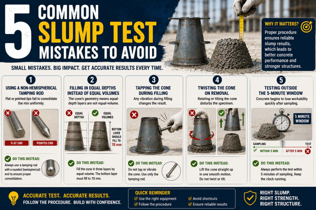
Small procedural errors produce unreliable results. These 5 mistakes come up most often on site:
- Using a non-hemispherical tamping rod — flat or pointed tips fail to consolidate the mix uniformly; always verify your rod has a rounded end
- Filling in equal depths instead of equal volumes — the cone’s geometry means equal-depth layers are not equal-volume; the bottom layer must fill to 70 mm
- Tapping the cone during filling — any vibration during filling changes the result; use only the tamping rod
- Twisting the cone on removal — lift the cone straight up in one clean motion; any rotation disturbs the specimen
- Testing outside the 5-minute window — concrete sampled more than 5 minutes ago gives lower-than-actual slump; always keep the clock running from sampling
Conclusion
The concrete slump test is a 2-minute field procedure with real structural consequences. Done correctly per ASTM C143 or IS 1199, it catches mix problems before pour — not after. A true slump within the specified range confirms the concrete is workable enough to fill forms and consolidate around steel, without sacrificing strength.
Know your 3 slump types. Understand the 6 factors that shift your reading. Use the acceptable value table to verify the mix matches the application. And when in doubt, reject the batch — the cost of a failed pour is always higher than the cost of proper testing.